- Adjust Design Grid
- Turn on Grid Counting feature
Quick Tips:
- Activate Design Grid through the Measure Tool dialog
- Open this dialog by clicking the box in the top left corner of the grid
- Set the spacing exactly, using the dialog
- Set the spacing manually using the arrows on the grid
- To activate Grid Counting, start with the Count Tool
Detailed Instructions:
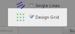
To start using the Design Grid, go through the Item Creator to get to
the Measure Tool dialog. Before measuring, check the Design Grid checkbox.
You may utilize the Grid Counting feature when using the Count tool. It allows
super fast counts of evenly spaced symbols in a row or a grid. After you start
measuring, you should see the grid over top the plan sheet. From here, you can
adjust the grid using the arrows on the upper right and lower left corners.
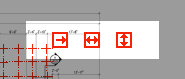
The first of the three arrows adjusts the area of the grid that is displayed;
drag this arrow to the right or downward. The grid area is automatically adjusted as
you pan and zoom but the button allows fine tuning.
The middle arrow adjusts
the spacing of the grid crosshair. You can adjust the spacing by dragging with
the left mouse, or you can set an exact value by entering it in the Design
Grid dialog. The last arrow will adjust the rotation of the grid. The rotation
is limited to just over 45 degrees. If you need it rotated more than that, just
rotate it the other direction.
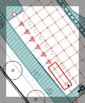
You move the origin of the design grid by dragging the Control Handle (the little
square on the top left). Place the bottom right corner of the Control Handle on
your starting point. For example, if you need to use the Design Grid to space out
sprinkler heads at even intervals, place the origin of the grid at the first
head. Or if you are counting light fixtures, place it on the first fixture.
After adjusting the grid to your design or layout on the sheet, click on the Control
Handle to open the Design Grid dialog. Here you can review and verify the grid spacing
or turn on grid counting. You can also turn on or off the grid at any time while
measuring this way. The grid can be used as a spacing reference while using the line
tool, or with the Grid Counting feature, you can use it to quickly and accurately
layout count symbols.
To use the counting feature, press the Grid Counting button. Simply draw a rectangle
around the grid crossings you need to count. Start up and left of the first grid
crossing and click. Then as you move the mouse you will see your options for how
many grid crossings to include in your count. You may select several in a row or
several rows and columns. You may even draw around a single grid crossing at a time
to precisely place the count symbol.
Once the selection is finalized, click again, and there will be a count symbol for
each of the grid crossings selected. It may take a few tries to get the hang of it,
just press the undo key ("3" on your keyboard) to reverse the count if you need to.
If you notice that the symbols are the incorrect size, simply press the "+" or "-"
keys (on the right end of your keyboard) to increase or decrease the size so they
are displayed properly.
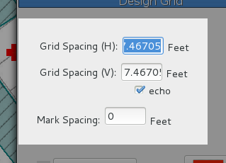
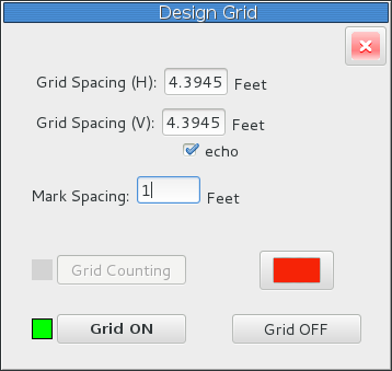
In the Design Grid dialog, you can specify the spacing of the grid. Clicking the
"echo" checkbox causes the vertical grid spacing to be equal to what the horizontal
spacing is set to. The Mark Spacing field controls the reference marks in between
the Grid Crossings. For example if you have a Grid Crossing every 10 feet, you can
set the Mark Spacing at 5 feet to show a tick mark at the halfway point. Or you can
set it to 2 feet to have 4 tick marks in between, one every two feet. This allows
the grid to act as a ruler on the sheet. Setting this equal to "0" will eliminate the
Marks on the grid, and you will only see the main Grid Crossing points.
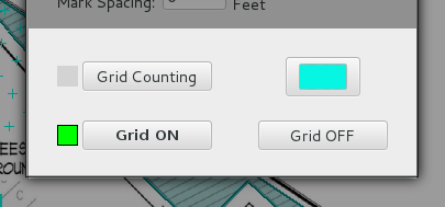
The color selection function on the dialog is to change the color of the grid, to increase
visibility if it is overlapping a markup of the same color, or to just change it to your
preference. The two buttons on the bottom allow you to turn the grid on or off. Once you
make a selection the dialog will close, and even if you have turned the grid off, you will
still see the small square in the upper left corner, in the color selected, which you can
click to reopen the dialog.