QuickEye Main Page
/
Help Topic List
/
Design Grid
QuickEye Estimator Help Topic:
Measure Tool Dialog
 Dialog purpose:
- Start measure sequence
- Revisit Scale
- Activate Design Grid
Quick Tips:
- Rectangle Area and Polygon Area both produce area (such as
Sq. Ft.), and perimeter as length.
- Rectangles are drawn by placing two separate points
on opposite corners.
- The Polygon Area tool defines an area with a series
of points around the perimeter of odd shaped spaces.
- Multiple measurements in the same Group, have their results
summed together.
- As you finish drawing an Area or Line measurement, press the
"Next" command to start the next in the series; the number 2
key.
- If a point is misplaced, press the Undo command; the number
3 key.
- When all the measurements are complete, go back to "Item
Creator" with the number 4 key.
- In Measure Tool, Press "Start" to proceed with the selected settings.
- Return to the "Measure Tool" dialog with the number 1 key.
- "Apply + Continue" can be used to adjust line thickness or
symbol size of just drawn measurements, and then resume
measuring.
Detailed Instructions:
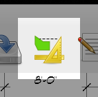
To open the Measure Tool dialog box, choose the Item Creator icon
from the main window toolbar. This will open the
Measure Scale
dialog the first time (because the scale has not been set for the sheet).
Then the
Item Creator
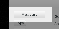
dialog box will open. Create a new Measurement Group or select an
existing one that you want to draw measurements into. Then press the
Measure button in the top-left corner.
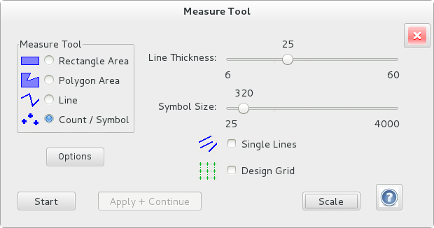
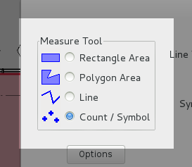
Now that the Measure Tool dialog is open, first pick the Measuring
Tool you wish to use, by selecting it on the left. Rectangle Area
and Polygon Area both produce area (such as Sq. Ft.), and perimeter
as length.
 Mark-Up Adjustments:
Before you start measuring, you may want to adjust the line thickness.
This affects the perimeter line of Rectangle and Polygon measurements
and the line thickness of Length measurements. If you are going to use
the Count tool, the symbol size adjusts the size of the Count symbol
drawn on the sheet with each click.
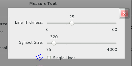
In both cases, the sizes are indicated in approximate, thousandths of an
inch. The actual number is not real important, because you usually
adjust it by experimenting, to produce the look you want.
The symbol size and line thickness are also adjusted as you draw, by
pressing the plus (+) and minus (-) keys on the keyboard.
After everything is selected, press the Start button in the bottom
left hand corner.
Measure Tool Functionality:
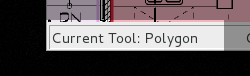
When you press start, the Measure Tool dialog will close, taking you
back to the main window with your selected drawing sheet open. In the
Status Bar, on the bottom of the main window, you will see the current
tool. As you draw measurements, this will be followed by the
measurement totals.
Notice that your cursor over the drawing is now a set of crosshairs.
Click your left mouse button to place a point. If you are zoomed out to
less than 45%, the view will magnify, while the left button is held down,
so that you can precisely place your point. The system is designed for
accuracy. You can draw quickly, ignoring the magnified view, or for
high accuracy, you can hold down the left button and adjust the
position of the crosshairs before you let up. On the right end of the
Status Bar, you will see your current Zoom percentage.
- Rectangles are drawn by placing two separate points on
opposite corners.
- The Polygon Area tool defines an area with a series of
points around the perimeter of the space, at each corner.
- The Line tool measures length by placing two points, or a longer
series of points along a route.
- The Count function places a symbol around each point you
place and produces the total count.
If a point is misplaced, press the Undo command; the number
3 key. As
you finish drawing an Area or Length measurement, press the "Next"
command to start the next in the series; the number
2 key (not needed
for Rectangle or Count).
When the next command is issued while drawing with the Polygon Area
tool, a new line will appear between the last point you placed and the
first point of the area, to close the shape and fill it with color. Then
you may proceed with the rest of the areas of the Measurement Group.
Multiple measurements in the same group (all for the same item) have
their results summed together. For example, with the Rectangle Area
tool, the total Sq. Feet and the total Perimeter of all the rooms traced.
You may also close a polygon by clicking on the first point. And you can
cut off a length measurement by clicking on the last point again.
To work with the resulting quantites and finish building the Item, return
to
Item Creator.
Press the number
4 key or click on the toolbar icon. There you
will specify the Item or Assembly
represented by the summed quantities from the Measurement Group, and
create a new Measurement Group for the next Item.
These command and shortcut keys, function anytime you are working with a
drawing, while no dialog boxes are open. For a cheat-sheet of controls
and shortcuts, please check our
QuickEye
Estimator Controls page.
Correcting/Changing Measure Settings:
As mentioned above, the symbol size and line thickness can be adjusted
as you draw, by pressing the plus (+) and minus (-) keys on the keyboard.
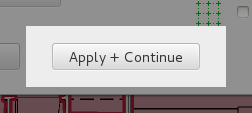
You may also return to the Measure Tool dialog, adjust the sliders and
then press the
"Apply + Continue" button. Your new settings
will apply to the measurement series you just drew, and then you can
continue drawing the rest. The shortcut to return to the Measure Tool
dialog is the number
1 key on the keyboard.
The other shortcut keys that apply to drawing measurements is for
rotating symbols.
E and
R rotate a symbol left and right by 90 degrees
per keypress. The next keys on either side rotate 2 degrees at a time. The
W key to rotate left (Counter-Clockwise) 2 degrees, and the
T key
to rotate right 2 degrees. This gives you full control over how the symbol
looks if you have a directional symbol such as an Elbow or a Sprinkler Head
symbol. You can remember it by thinking
R for Rotate Right. All four are
in a row and should work well for quickly setting the rotation.
The rotation will apply to the most recent symbol only and will also be
used for successive symbols, until you set a different rotation.
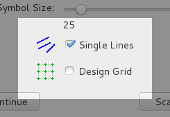
Accessing Single Lines and Design Grid:
If your measurement requires single line segments only, set the Single
Lines checkbox. This eliminates the need to end every segment manually.
This results in only needing two clicks per line, but all the lines
will be single. While drawing you may
toggle "Single Lines" mode by pressing the
S key. The current mode
is indicated on the status bar at the bottom of the main window.
Checking the Design Grid checkbox, turns on the Design Grid. Please check
out our
Design Grid
page to learn about this powerful tool.